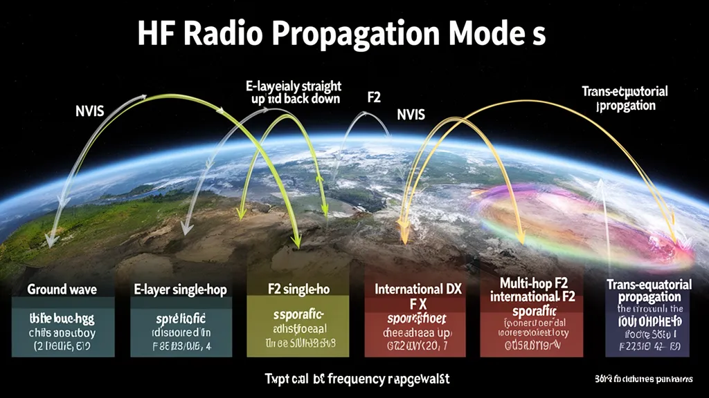
What HF Propagation Modes Are and Why They Matter
HF signals travel from transmitter to receiver via several distinct physical mechanisms — ground wave, multiple ionospheric layers, scatter from meteors and the aurora, and even reflection from the Moon. Each mode has a characteristic frequency range, typical path distance, reliability, and sensitivity to solar activity. Understanding which mode is at work on a given contact is the foundation of systematic propagation analysis.
No single propagation mode dominates all situations. A 160m NVIS net and a 10m transpacific DX contact operate by completely different physics. Recognizing which mechanism is in play on any given band tells you what conditions to check, what antennas to use, and what to expect when conditions change.
Pro Tip: Not sure which propagation mode is active on a contact? Check DXRadar’s best bands now page — it synthesizes live PSKReporter spot density with solar conditions to show which modes are currently producing contacts on each band. For space weather context affecting all modes, visit the solar weather dashboard.
The sections below cover every major mode in the order an operator is most likely to encounter them — from the most basic and reliable to the most exotic and elusive.
Ground Wave: The Reliable Short-Range Mode
Ground wave propagates along Earth’s surface by inducing currents in the ground, diffracting around the curvature of the Earth. It is effective primarily below 3 MHz and delivers reliable, 24/7 regional coverage with no solar dependence whatsoever (ITU-R P.368-9).
Typical range is 100–500 km, depending on:
- Frequency: Lower frequencies propagate farther. At 1.8 MHz, ground wave can reach 600 km over sea water. At 28 MHz, ground wave is essentially negligible beyond 20 km.
- Ground conductivity: Salt water is an excellent conductor (σ ≈ 4 S/m) and dramatically extends ground wave range. Poor, dry soil (σ ≈ 0.001 S/m) sharply limits range.
- Antenna polarization: Vertical polarization propagates as ground wave; horizontal polarization is strongly attenuated.
On the air, ground wave contacts have a characteristic stability. There is no QSB, no flutter — just a steady signal that doesn’t change minute to minute. If you’re working a 160m regional net at night and a station 300 km away is rock-solid S8 with no fading, you’re working ground wave. During the day on 40m, stations within 200 km may be arriving partially via ground wave and partially via ionospheric modes — the combination can cause slow, deep fading as the two paths interfere.
Bands where ground wave matters: 160m (1.8 MHz), 80m (3.5 MHz), and to a lesser extent 40m (7 MHz) at close ranges.
On 160m and 80m, a vertical antenna with a good radial system outperforms a horizontal dipole for ground wave work because vertical polarization is required for ground wave propagation. If your goal is regional coverage on Topband, invest in the ground system, not just the antenna element.
F2 Skip: The Dominant Long-Distance Mode
F2 skip is the primary mechanism behind virtually every HF DX contact above 7 MHz. Single-hop F2 covers 1,500–4,000 km; multiple hops extend range to 20,000 km and beyond. The F2 layer persists day and night, making it the only ionospheric mode capable of round-the-clock worldwide propagation (ITU-R P.533-14).
The mechanism: solar EUV radiation ionizes atomic oxygen at 200–500 km altitude, creating the F2 layer. A transmitted signal strikes the layer at an oblique angle, refracts back to Earth, and arrives at the target. The maximum usable frequency (MUF) for a given path equals foF2 × sec(θ), where θ is the elevation angle at the reflection point — higher launch angles mean shorter hops and lower MUF.
F2 propagation has strong solar dependence:
- SFI below 70: 10m and 12m essentially dead for F2 DX; 15m marginal; 17m and 20m reliable.
- SFI 100–120: 10m opens for daytime paths within 5,000 km at favorable latitudes.
- SFI above 150: 10m supports worldwide propagation; 6m occasionally opens via F2 at equinox.
On the air, F2 signals on 10m at solar maximum have a distinctive sound: very strong (often S9 or better), moderately stable, with slow QSB over minutes. If you’re at a North American QTH and hear European stations booming in on 28 MHz at 14:00 UTC in December with SFI above 160, that’s F2 skip in action — specifically benefiting from the F2 winter anomaly.
Single-hop distance: For a signal launched at a 6° elevation angle, the skip distance to the F2 layer at 300 km altitude is approximately 3,500 km. For an elevation of 15°, the hop shortens to about 2,000 km. Multiple hops (see the dedicated section on multi-hop propagation) cover the remaining distance to the antipodes.
F1 Layer Skip: The Daytime Shorter-Distance Mode
The F1 layer occupies 150–200 km altitude and exists only during daylight hours. It supports somewhat shorter skip distances than F2 — typically 800–2,500 km — and has lower maximum electron density, limiting its MUF to lower frequencies.
In practice, the F1 layer rarely dominates on the amateur bands. When the F2 layer is well-developed (daytime, reasonable SFI), F2 skip dominates at the same frequencies. The F1 layer becomes more relevant during:
- Low solar flux periods when F2 foF2 is marginal for higher frequencies
- Early morning and late afternoon when the F2 layer is building or decaying
- Path geometries where F1 geometry happens to be more favorable
From an operating standpoint, you will rarely distinguish an F1 contact from an F2 contact without ionosonde data. The F1 layer disappears entirely after sunset.
E-Layer Skip: Consistent but Limited Range
The regular E layer sits at 90–120 km altitude and supports HF skip on lower frequencies. E-layer skip typically produces contacts at 800–2,000 km — longer than Es but shorter than typical F2 distances (ARRL Handbook, Propagation chapter).
Unlike sporadic-E, the regular E layer is predictable. It:
- Forms during daylight from solar photoionization of molecular oxygen and nitrogen
- Disappears at night
- Peaks around local solar noon
- Supports frequencies roughly up to 4–7 MHz on oblique paths
For most amateur HF bands above 7 MHz, the regular E layer plays a supporting role rather than a dominant one. It contributes to medium-distance daytime paths on 40m and 60m. On 80m, the E layer is often the dominant daytime mode for contacts in the 500–2,000 km range.
The regular E layer does not have the dramatic bursts of ionization that make sporadic-E famous, but its consistency makes it a reliable workhorse for regional daytime nets on lower HF.
Sporadic-E: The Unpredictable Band Opener
Sporadic-E (Es) is patchy ionization concentrated in thin clouds within the E layer at 90–120 km altitude. It produces single-hop distances of 500–2,500 km and is especially prominent on 6m, 10m, and occasionally 12m (NOAA SWPC; ARRL).
The exact cause of Es ionization clouds remains partially understood. Leading theories invoke wind shears creating convergence of metallic ions deposited by meteors. What is well established:
- Northern Hemisphere peak: May through August, with June–July most intense
- Secondary peak: November–December (less pronounced)
- Southern Hemisphere peak: November through January
- Frequency of occurrence: Multiple times per week during peak season, though individual openings are short (30 minutes to several hours) and geographically narrow
On the air, Es has a distinctive signature: stations that were completely absent suddenly appear at signal levels that would be remarkable even on a good F2 day. A European station 1,800 km away might go from nothing to S9+30 dB in under a minute on 6m. The opening may be directionally narrow — you hear Germans but not French stations, because the Es cloud is positioned over central Europe and the geometry to France doesn’t hit the cloud. Rapid QSB (deep fades on 10-second timescales) is characteristic.
Es can also occur in multi-hop configurations (two Es clouds in succession), extending range to 4,000–5,000 km on 6m. During strong multi-hop Es, transatlantic 6m contacts from Europe to North America occur several times per summer.
When you hear Es starting on 10m with signals from 1,200 km, immediately check 6m. Es that’s refracting 28 MHz signals at a 1,200 km hop distance likely has sufficient electron density to support 50 MHz as well. The Es cloud that opens 10m and the one that opens 6m don’t have to be different clouds — they’re often the same event.
NVIS: Coverage in the Skip Zone
Near Vertical Incidence Skywave (NVIS) fills the coverage gap between ground wave (max ~500 km) and normal skip (min ~800 km). By radiating signals nearly straight up (elevation angles above 60° from horizontal), an NVIS antenna illuminates the ionosphere above the transmitter, which then re-radiates the signal omnidirectionally back down. Coverage is a roughly circular footprint with 0–500 km radius (ARRL NVIS technical series).
Effective NVIS frequencies: 2–10 MHz, with the practical sweet spot usually 3–7 MHz depending on foF2. The upper limit is foF2 itself — if foF2 is 6 MHz, you cannot do NVIS above 6 MHz because signals above that frequency punch through to space. The lower limit is D-layer absorption, which makes frequencies below 2 MHz inefficient during daylight hours.
NVIS antennas: a horizontal dipole at 0.1–0.15 wavelength height (for example, about 6 m high on 40m) provides excellent near-vertical radiation. This is counterintuitively the opposite of what you’d want for DX work — a low dipole for DX is wrong, but a low dipole for NVIS is correct.
On the air, NVIS contacts have excellent signal levels within the coverage zone. Stations 200 km away may be S9 while 800 km stations are in the skip zone and completely absent. During EmComm activations or regional nets on 40m and 60m, an operator who understands NVIS can maintain contact with stations within the state or province even when skip overshoot would normally make those contacts impossible.
Operator’s Verdict: NVIS is the right tool when you need coverage within 500 km and skip distance would overshoot. Low dipole on 40m or 60m, daytime operation, foF2 above your operating frequency. It is standard EmComm doctrine for a reason.
Trans-Equatorial Propagation: The Equinox Mode
Trans-equatorial propagation (TEP) is a specialized F2 enhancement that occurs near the magnetic equator. Signals travel from stations at approximately ±10–25° magnetic latitude across the magnetic equator and are returned by anomalously high electron density on the other side, enabling contacts at 2,500–6,000 km on 10m, 6m, and occasionally 2m.
The mechanism involves the equatorial fountain effect, which concentrates electron density into two bands (the equatorial ionization anomaly, EIA) at approximately ±15° magnetic latitude. During strong TEP conditions, these density peaks can be high enough to support 50 MHz and sometimes 144 MHz propagation — frequencies that would normally punch straight through the ionosphere.
TEP has clear seasonal and time-of-day signatures:
- Equinox peaks: March–April and September–October
- Time of day: Typically 15:00–22:00 local time at the midpoint
- Who benefits: Stations in Mexico, Brazil, South Africa, India, Southeast Asia, Japan (southern islands), and the Pacific — latitudes close to the magnetic equator
On the air, TEP signals on 6m have a characteristic fluttery quality, often with a longer and more complex flutter pattern than sporadic-E. The propagation can be bilateral (both stations on opposing sides of the equator) or unilateral (stronger in one direction). During an equinox TEP opening, European stations south of about 40° N may hear South African stations on 50 MHz booming in at S9+.
Aurora Scatter: The Raspy DX Mode
Aurora scatter propagates signals by reflecting them off the turbulent, ionized curtain of the aurora borealis (or australis). It is primarily a VHF mode — 50 MHz and 144 MHz — though 28 MHz aurora scatter is possible during intense geomagnetic storms (ARRL).
The key characteristic of aurora scatter is signal distortion. The scattering medium is turbulent and moving, which Doppler-spreads the signal. On CW, an aurora scatter signal sounds like a harsh, buzzing rasp rather than a clean tone. SSB voice is generally unintelligible due to the Doppler spreading. CW, MSK144, and FSK441 are the practical modes.
Distances: typically 500–3,000 km, with the aurora acting as a reflector. Two stations in different directions from the aurora can work each other by both pointing their beams toward the aurora curtain rather than at each other.
Aurora scatter peaks during geomagnetic storms (Kp 5 or higher by NOAA G-scale definitions). During a G2 or G3 storm, European stations on 144 MHz regularly work aurora scatter paths of 1,500–2,000 km. The aurora’s latitude determines who can participate — during severe storms (Kp 7+), the aurora moves to mid-latitudes and operators at 45–55° N can work aurora scatter. During weaker events, it may be limited to stations above 60° N.
Meteor Scatter: Milliseconds of Contact
Meteor scatter (MS) uses the ionized trails left by meteors entering the upper atmosphere at 80–120 km altitude. Each meteor creates a brief ionized column that reflects radio signals for milliseconds to a few seconds. Concentrated during meteor showers (Perseids in August, Leonids in November, etc.) but present 24/7 from sporadic meteors.
Primary frequencies: 50 MHz and 144 MHz. The geometry and ionization density favor VHF; HF meteor scatter is theoretically possible but practically dominated by other modes.
Practical meteor scatter requires specialized digital modes because even “overdense” (bright meteor) trails last only a few seconds. The modes in use:
- MSK144: Current standard, developed by Joe Taylor K1JT. Sends a full exchange in 144 ms bursts.
- FSK441: Older standard, still in occasional use.
- High-speed CW: Used historically; now largely replaced by digital modes.
On the air, meteor scatter contacts on 2m are infrequent outside of shower peaks — you may hear a burst of signal that lasts half a second and then silence. During the Perseid peak, 2m MS contacts are fairly routine over paths of 800–2,000 km, even between modest stations.
For meteor scatter, point your beam at 60–70° elevation toward the radiant of the shower, not at the horizon. You’re illuminating the altitude where meteor ionization occurs, not trying to make a line-of-sight contact.
Tropospheric Ducting: VHF Over the Horizon
Tropospheric ducting is a VHF/UHF mode operating in the lowest 2 km of the atmosphere. Temperature inversions create layers where the refractive index decreases sharply with altitude, trapping signals in a duct that guides them along the Earth’s surface at low loss. Typical range: 500–3,000 km on 50 MHz–1.3 GHz (ARRL VHF/UHF Propagation).
Ducting conditions form when:
- A warm air mass overrides cooler air (warm front aloft)
- High-pressure systems create subsidence inversions
- Coastal regions experience marine layer formation (common in summer mornings)
On the air, ducting on 2m or 70cm sounds dramatically different from normal conditions. Stations 1,000 km away arrive with signal levels typical of locals — S7–S9 with no flutter, no distortion, just a strong, steady signal. If you suddenly hear UK stations on 144 MHz from France or western Europe, or southern US stations on 2m from the Midwest, a tropospheric duct is almost certainly the cause.
Ducting is unpredictable, forming and collapsing over hours. The website dxinfocentre.com and the APRS network provide real-time ducting event reports from European and North American operators.
Moonbounce (EME): The Ultimate Long Path
Earth-Moon-Earth (EME) propagation reflects signals off the lunar surface, with a 2.4-second round-trip delay at the speed of light. The Moon is at approximately 384,000 km average distance, and the path introduces roughly 252 dB of free-space path loss at 144 MHz — one of the highest path losses routinely overcome in amateur radio (ARRL EME technical series).
EME is practical from 144 MHz upward, with 144 MHz, 432 MHz, 1.2 GHz, and 2.3 GHz being the most active amateur bands. At 50 MHz, EME is very difficult and requires exceptional antennas; at 10 GHz, the Moon’s small angular size and high-gain dish antennas make it practical for moderate stations.
The digital mode JT65 (and its successors Q65 and MSK144 at 2m) made EME accessible to stations that previously could not work it. Before JT65, EME required large antenna arrays and high power. Today, a single 17-element Yagi at 144 MHz and 100W can complete EME contacts using Q65.
On the air, the 2.4-second round-trip delay is perceptible — if you watch the waterfall, your own echo comes back clearly after the signal completes. Doppler shift from lunar libration causes a slight frequency spreading. EME contacts are not DX in the geographic sense — you’re not talking to a station in another country — but the propagation challenge is among the most demanding in amateur radio.
Propagation Mode Comparison
| Mode | Frequency Range | Typical Range | Reliability | Solar Dependence |
|---|---|---|---|---|
| Ground wave | DC–3 MHz | 50–500 km | Very high, 24/7 | None |
| F2 skip | 7–30 MHz (peak) | 1,500–20,000 km | High at solar max | Strong |
| F1 skip | 5–15 MHz | 800–2,500 km | Moderate (daytime) | Moderate |
| E-layer skip | 4–8 MHz | 800–2,000 km | Moderate (daytime) | Low |
| Sporadic-E | 28–144 MHz | 500–2,500 km | Low (seasonal) | Very low |
| NVIS | 2–10 MHz | 0–500 km | High when foF2 permits | Moderate |
| TEP | 28–144 MHz | 2,500–6,000 km | Seasonal/equinox | Low–moderate |
| Aurora scatter | 50–432 MHz | 500–3,000 km | Storm-dependent | Geomagnetic |
| Meteor scatter | 50–144 MHz | 500–2,000 km | Low (shower peaks) | None |
| Troposcatter/duct | 50 MHz–1.3 GHz | 200–3,000 km | Weather-dependent | None |
| EME | 144 MHz–10 GHz | ~760,000 km (one way) | High (hardware-limited) | None |
Frequently Asked Questions
What is the most reliable HF propagation mode?
Ground wave is the most reliable HF propagation mode — it operates 24/7 with no solar or ionospheric dependence, at frequencies below 3 MHz and ranges up to 500 km. For long-distance HF (above 1,000 km), F2 skip via the 20m band is the most reliable mode, persisting day and night through the solar cycle, though it degrades during geomagnetic storms.
What propagation mode works when the bands seem dead?
When upper HF bands (10m–15m) are dead due to low solar flux, try 40m or 80m via F2 or E-layer skip during daytime for medium-distance contacts, or 160m–80m via ground wave for regional coverage. Sporadic-E can open 10m and 6m regardless of solar flux, but it’s unpredictable. Check the current SFI and Kp before drawing conclusions about what modes are theoretically available.
Can you tell which propagation mode is active by the sound of the signal?
Experienced operators can often identify the mode by signal characteristics. Ground wave: rock-steady, no QSB. Normal F2: slow, gentle QSB over minutes. Sporadic-E: fast, deep QSB; signals appear and disappear abruptly. Aurora scatter: distinctive raspy, buzzy tone on CW. Troposcatter: strong, stable, similar to ground wave but over VHF. Meteor scatter: burst of signal lasting less than a second.
Does geomagnetic activity affect all propagation modes the same way?
No. Geomagnetic storms (elevated Kp) degrade F2 propagation — especially at high latitudes (above 55° N or S) and on trans-polar paths. NVIS and lower-HF modes are less affected at mid-latitudes. Aurora scatter and E-layer backscatter on VHF actually improve during storms. Ground wave is completely unaffected by geomagnetic activity. EME is not affected by geomagnetic conditions at all.
What is the skip zone and how does it affect propagation?
The skip zone is the area between the maximum ground wave range and the minimum sky-wave skip distance where neither mode provides coverage. On 20m from a North American QTH, stations within about 200 km (reachable by ground wave) and beyond about 1,000 km (reachable by F2 skip) may be workable, but stations at 300–800 km fall in the skip zone and may be completely inaudible. NVIS deliberately fills the skip zone by using near-vertical radiation to cover that intermediate distance.