What Multi-Hop Propagation Is
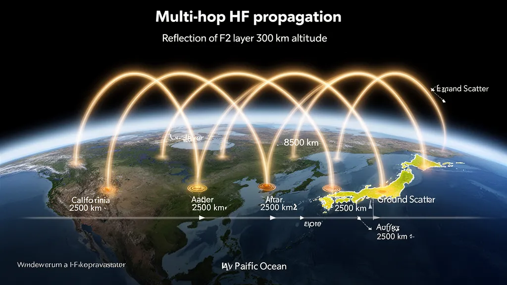
Multi-hop propagation is the mechanism that extends HF contacts beyond the 3,500–4,000 km maximum distance of a single F2 reflection. A signal reflects off the F2 layer, returns to Earth, reflects off the ground, rises again to the F2 layer, and repeats — each cycle constituting one hop — until the signal arrives at the destination. Typical DX contacts at 10,000–20,000 km require 3–6 hops depending on F2 layer height, launch angle, and frequency (ITU-R P.533-14).
Understanding multi-hop mechanics explains several things that otherwise seem arbitrary: why some transoceanic paths open more easily than others, why the same path can be 10–15 dB stronger one day versus the next, and why long-path contacts sometimes beat short-path even to the same station.
Pro Tip: Use DXRadar’s solar weather page to check Kp before chasing long-distance multi-hop DX. If Kp exceeds 4 and your path crosses high latitudes, one of your intermediate hop legs may be degraded. Switch to best-bands-now to find alternative bands with active propagation.
Single-Hop Geometry: The Building Block
Before examining multi-hop, the geometry of a single F2 hop establishes the baseline.
For a signal launched at elevation angle α from a transmitter, the reflection point is at approximately:
Single-hop distance (km) ≈ 2 × h × cot(α)
where h is the F2 layer virtual height in kilometres (typically 250–400 km for the F2 layer). At a low elevation angle of 5°, with an F2 layer at 300 km height:
Distance ≈ 2 × 300 × cot(5°) ≈ 2 × 300 × 11.4 ≈ 6,860 km
In practice, ray optics and the refractive index gradient of the ionosphere limit effective single-hop distances to 1,500–4,000 km for most amateur HF contacts, with 3,000–3,500 km being the typical maximum for a strong single-hop path on 20m. Very long single hops (above 4,000 km) require unusually low launch angles and a well-elevated F2 layer.
For a given path longer than about 3,500 km, the signal must complete multiple hops. A path from FN31 (northeastern USA) to VK2 (eastern Australia) is approximately 16,500 km via short path — requiring a minimum of 4 hops at 3,500 km each, or more likely 5 hops given the specific path geometry.
Ground Reflection Loss: The Cost Per Hop
Each time a multi-hop signal returns to Earth, it reflects off the surface. The reflection is not lossless — energy is absorbed depending on ground conductivity at the reflection point.
| Ground Type | Reflection Loss (per hop) |
|---|---|
| Sea water (σ ≈ 4 S/m) | 2–4 dB |
| Moist, cultivated land | 5–7 dB |
| Average mixed terrain | 6–8 dB |
| Rocky, mountainous terrain | 8–10 dB |
| Ice (Arctic/Antarctic) | 4–6 dB |
For a 4-hop path from North America to Australia via the Pacific, ground reflection points typically fall over ocean water. Four reflections at 3 dB each accumulate 12 dB of ground reflection loss — significant, but manageable with a high-SFI F2 layer. The same path routed over land (if possible) would add much more.
This explains why transoceanic paths are often stronger than transcontinental paths of similar length. The North America to Japan path crosses the Pacific (predominantly sea reflections), while a similar-distance path from North America across the interior to the Middle East crosses considerable land (higher reflection losses).
When you have the option of short path versus long path to a DX station, check which route crosses more ocean. A long path that crosses the Atlantic or Pacific may outperform a short path that crosses multiple continents, particularly on lower HF bands where ground reflection losses are higher relative to path MUF.
Night vs. Day: F2 Height and Extended Single-Hop Distance
The F2 layer’s virtual height increases at night as the lower ionosphere decays and the reflection point moves to higher altitudes (Goodman 1992; ARRL Handbook). This has a direct geometric effect: a higher reflection height increases single-hop distance for the same launch angle.
During the day, the F2 layer typically reflects at a virtual height of 250–350 km. At night, the virtual height may increase to 350–450 km on some paths. This extends the maximum single-hop distance from about 3,500 km to potentially 4,500–5,000 km.
The practical consequence: on a long path requiring 5 daytime hops, the night conditions might cover the same distance in 4 hops, accumulating one fewer ground reflection loss. This is one reason why some DX paths that barely open during daytime become reliably strong around the gray line, when one or both ends of the path are in transition between day and night F2 conditions.
Path Geometry: Why Some Routes Beat Others
Multi-hop propagation is sensitive to the specific route taken. Two paths between the same endpoints may have different numbers of ground reflections, different ground conductivity at reflection points, and different ionospheric conditions along each leg.
Short Path vs. Long Path
Every point on Earth has a short path (minor arc great circle) and a long path (major arc great circle). For non-antipodal stations:
- Short path + long path = approximately 40,000 km (circumference of Earth)
- A short path of 15,000 km has a long path of 25,000 km to the same station
The long path is longer, so it requires more hops. However, if the long path crosses more ocean while the short path crosses continental interior, the long path may actually arrive with comparable or stronger signal due to lower accumulated ground reflection losses. During major DX contests, experienced operators always compare short and long path bearings — not assuming short path is always better.
Path Diversity: F2 Conditions Along Each Leg
Multi-hop paths traverse multiple ionospheric regions, each with its own foF2 and electron density profile. If any single leg of a multi-hop path has foF2 below the operating frequency, that leg cannot support the propagation mode and the path fails — regardless of how good conditions are on the other legs.
This explains why long multi-hop paths can open and close rapidly. A geomagnetic disturbance that depresses foF2 over one ocean region — even if your local conditions are excellent — can close an otherwise open multi-hop path. When a 20m path to a distant DX station that was S7 drops to nothing over 15 minutes, and the SFI hasn’t changed, the most likely cause is ionospheric disturbance on one of the intermediate hop legs.
Chordal Hops: The Rare Efficient Mode
The chordal hop is a propagation mode where the signal travels within the F2 layer for a significant portion of the path, without returning to Earth between entry and exit. The signal enters the ionosphere at one end of the path, refracts along a curve that stays within the high-density region of the F2 layer, and exits at the far end without the ground reflection penalty.
Conditions required for a chordal hop:
- High F2 electron density: Needed to create the refractive curvature within the layer
- Favorable path geometry: The path must align with the geometry of the F2 layer’s horizontal extent
- Appropriate frequency: Below the critical frequency at all points along the intra-ionospheric path
Chordal hops are associated with unusually strong signals on long paths — the absent ground reflection loss makes the signal significantly stronger than conventional multi-hop theory predicts. They are invoked to explain cases where measured signal levels are 10–20 dB stronger than VOACAP or similar models predict. They are not reliably predictable but are well-documented in the HF propagation literature (Goodman 1992; ITU-R P.533).
Some transpolar paths that should theoretically be extremely lossy (multiple land reflections over Arctic terrain, geomagnetic absorption in the polar cap) instead produce strong signals in certain conditions — chordal hop geometry is one proposed explanation.
A Real Multi-Hop Example
To illustrate: a 20m SSB contact between FN31 (New England, northeastern USA) and VK2 (New South Wales, Australia) via the short Pacific path covers approximately 16,500 km.
With a typical F2 hop distance of 3,200–3,500 km:
- Number of hops needed: 5 (5 × 3,300 km = 16,500 km)
- Ground reflection points: 4 (after hops 1, 2, 3, and 4; the 5th hop lands at the destination)
- Ground reflection type: Predominantly Pacific Ocean — approximately 3 dB per reflection
- Accumulated reflection loss: 4 × 3 dB = 12 dB
- Free-space path loss at 14 MHz over 16,500 km: approximately 140 dB (FSPL = 32.44 + 20·log₁₀(14) + 20·log₁₀(16,500) ≈ 140 dB)
On a high-SFI day (SFI above 150), 20m conditions are favorable and the F2 layer along the Pacific path is well-ionized. Such a path can produce S7–S9 signals at both ends. The path typically opens around 10:00–11:30 UTC from eastern USA, depending on season — the time when the Pacific path geometry aligns both endpoints with adequate F2 illumination and the gray line sweeps across the path favorably.
Operator’s Verdict: Multi-hop propagation is not exotic or special — it is how virtually all HF DX contacts beyond 4,000 km work. Every transatlantic, transpacific, and transcontinental contact is a multi-hop event. Knowing the number of hops, the ground reflection conductivity along the route, and the F2 layer height along each leg tells you why a path opens, when it peaks, and how strong to expect signals to be.
Frequently Asked Questions
How do I know how many hops a path is using?
You cannot directly determine hop count from the received signal. VOACAP and similar propagation modeling tools estimate hop count based on path geometry and F2 layer height. As a rule of thumb: divide the great circle distance by 3,000–3,500 km to get an approximate hop count. Paths crossing 10,000–15,000 km are typically 3–4 hops; 15,000–20,000 km paths are 4–6 hops.
Why do multi-hop paths open and close so quickly?
Multi-hop paths require adequate foF2 at every hop along the route. A change in F2 conditions — geomagnetic disturbance, terminator movement as the day progresses, or wave activity in the ionosphere — on any single leg breaks the chain. The opening may last only 20–60 minutes as the terminator sweeps across one of the intermediate reflection points. This is why DX pile-ups on rare entities sometimes have very short windows; the multi-hop path geometry is only favorable for a limited time.
Does the mode (CW vs. FT8 vs. SSB) change which multi-hop paths are workable?
Mode affects minimum detectable signal, not the propagation mechanism. FT8’s approximate −20 dB SNR capability (in 2.5 kHz bandwidth) versus SSB’s +10 dB SNR requirement means FT8 can work paths with 30 dB more loss than SSB. In practice, this means FT8 can work some multi-hop paths during marginal conditions (lower SFI, partial illumination) that would be completely inaudible on SSB. The path geometry, hop count, and ground reflection losses are identical — only the signal-to-noise threshold differs.
What is the difference between multi-hop and scatter propagation?
Multi-hop propagation involves specular reflection — the signal bounces off the F2 layer and the Earth’s surface in a predictable geometric pattern, arriving at a specific bearing from the transmitter. Scatter propagation (E-layer scatter, F2 forward scatter) involves diffuse scattering from irregularities in the ionosphere or Earth’s surface, arriving from a range of angles with lower signal strength but greater flexibility in path geometry. Multi-hop produces stronger signals but requires specific geometric alignment; scatter is weaker but can provide coverage at angles where specular multi-hop geometry doesn’t apply.