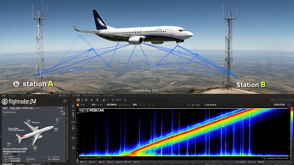
Operator’s Verdict: Commercial airliners reflect 144 MHz signals between stations 300–1,000 km apart. Works year-round regardless of propagation conditions. Use MSK144 + GlobeS flight tracking software to predict and use scatter windows. The most reliable extended VHF mode available on any day of the year.
How Aircraft Scatter Works
At 10–12 km cruise altitude, a wide-body airliner presents a metal structure approximately 60–80 metres across. At 144 MHz (wavelength ≈ 2 metres), the aircraft is hundreds of wavelengths in size — a substantial radar target. Its radar cross-section (RCS) is on the order of 100–1,000 square metres depending on aircraft type and aspect angle.
As the aircraft flies its route, it briefly enters a geometry where:
- Station A transmits a beam that illuminates the aircraft
- The aircraft reflects (scatters) energy toward Station B
- Station B receives the reflected signal
This forward-scatter geometry occurs when the aircraft crosses the specular reflection point — the bisector plane between both stations’ beams. For two stations 600 km apart, the reflection zone is a narrow region approximately 50–100 km wide along the flight path.
An aircraft transiting the specular zone at 900 km/h typically produces a reflection window of 20–90 seconds, depending on geometry. During this window, MSK144 can complete a full QSO.
Pro Tip: Aircraft scatter works year-round unlike sporadic-E or meteor scatter. Check DXRadar’s solar weather for current conditions — aircraft scatter is effective regardless of SFI or Kp. Use best bands now to find which VHF modes are active today.
The Doppler Shift Problem
An aircraft flying at 900 km/h toward the specular point produces a significant Doppler shift on the reflected signal. The shift depends on the component of aircraft velocity along the signal path:
- Aircraft approaching the specular point: positive Doppler (signal frequency increases)
- Aircraft at specular point: near-zero Doppler
- Aircraft departing: negative Doppler (signal frequency decreases)
At 144 MHz, Doppler shifts from aircraft scatter are typically 20–200 Hz (max ~240 Hz for a 900 km/h aircraft approaching head-on; 500 Hz would require supersonic flight), varying continuously throughout the scatter window. This frequency drift is visible on the WSJT-X waterfall as a tilted trace rather than a vertical stripe, and MSK144’s decoding algorithm handles this drift.
The characteristic “tone sweep” sound of aircraft scatter — a signal that sweeps in frequency over several seconds — is the Doppler shift made audible.
Planning with GlobeS
GlobeS (available from DL4MFM) is the standard software for planned aircraft scatter operations. It integrates:
- Live ADS-B flight data (via dump1090, OpenSky Network, or Flightradar24 API)
- Great-circle geometry calculation between your grid and target grid
- Aircraft position extrapolation to predict specular crossing times
- Bearing to point your antenna during the scatter event
Operating with GlobeS:
- Enter your station grid square and target station grid square
- Connect to ADS-B data source (a cheap RTL-SDR dongle running dump1090 provides local ADS-B data)
- GlobeS displays a timeline of upcoming aircraft scatter windows for that specific path
- For each window, GlobeS shows: aircraft callsign (ICAO hex), predicted scatter time (UTC), antenna bearing for the scatter point
- Pre-arrange a sked with the target station via ON4KST chat or email
- Both stations point antennas at the calculated bearing and start MSK144 transmission at the predicted time
Without coordination, aircraft scatter is hit-or-miss. With GlobeS and pre-arrangement, QSO completion rates become high even on marginal paths.
Equipment and Antenna Setup
Aircraft scatter does not require extraordinary antenna gain, but directionality matters for pointing at the scatter geometry:
Antenna: Any steerable Yagi with gain will work. The antenna bearing for aircraft scatter is typically NOT toward the target station — it points toward the specular reflection zone (roughly midway along the path, but offset by the scatter geometry). GlobeS calculates the correct bearing.
Mode: MSK144 exclusively. SSB voice is impractical for aircraft scatter due to the rapid signal onset, Doppler, and short window duration.
Frequency: 144.360 MHz (Europe) — same MSK144 calling frequency as meteor scatter.
Power: 100 watts is workable; 400–500 watts improves QSO completion for longer paths.
Aircraft Scatter vs. Meteor Scatter
Aircraft scatter and meteor scatter appear similar on the waterfall — both produce brief burst signals. Key differences:
| Feature | Aircraft Scatter | Meteor Scatter |
|---|---|---|
| Predictability | High (known flight paths) | Low (random for sporadic; predictable for showers) |
| Duration | 10–90 seconds per event | 10–500 ms per burst |
| Frequency | Year-round, daily | Best during major showers |
| Doppler | Slow sweep (100–500 Hz) | Instantaneous offset |
| Distance | 300–1,000 km | 800–2,200 km |
| Mode | MSK144 | MSK144 |
Aircraft scatter excels in winter and on days with no meteor shower, filling the calendar gap. Meteor scatter excels for long DX paths (1,000–2,200 km) where aircraft geometry can’t reach.
Busy Airlane Routes for Aircraft Scatter
The best aircraft scatter opportunities are along high-traffic airway routes where many flights transit the scatter zone per hour:
Europe: The North Atlantic track system passes over Ireland, UK, Iceland — useful for UK–Ireland–Scandinavia paths. The European core airways (Amsterdam–Frankfurt–Paris triangle) provide excellent scatter density for paths across that region.
North America: Transcontinental routes (coast-to-coast) and the busy northeast corridor (Boston–New York–Washington) provide regular scatter opportunities for stations in those regions.
Aircraft scatter is most productive for station pairs located along major airway routes. Two stations in rural Iceland or Pacific islands will have poor aircraft scatter opportunities regardless of technique — there simply aren’t enough transiting aircraft.
Aircraft scatter represents the “engineering” approach to VHF DX: using software, predictable traffic patterns, and digital modes to extract contacts from a propagation mechanism that was nearly impossible to exploit intentionally before 2010.
Frequently Asked Questions
What is aircraft scatter propagation?
Aircraft scatter (AS) is a VHF propagation mode where commercial airliners reflect radio signals between ground stations. An airliner flying at cruise altitude (10–12 km) can reflect 144 MHz signals between two stations located 400–1,000 km apart. The aircraft acts as a passive reflector — no special cooperation from the aircraft is required. As the aircraft moves along its flight path, a brief reflection geometry occurs where signals from station A hit the aircraft and are reflected toward station B. A typical aircraft scatter event lasts 10–90 seconds as the aircraft transits the reflection geometry. MSK144 digital mode can complete QSOs within single aircraft reflection windows.
How far can aircraft scatter reach on 144 MHz?
Aircraft scatter on 144 MHz typically enables contacts of 300–1,000 km. The maximum range is geometrically constrained by the aircraft cruise altitude (10–12 km) and the requirement for both station beams to illuminate the aircraft simultaneously. At 10 km altitude, the maximum theoretical scatter range for a single reflection is approximately 700–750 km (geometric horizon from the aircraft ≈ 357 km each side; 1,200 km would require ~28 km cruise altitude). Most operational aircraft scatter contacts occur at 400–800 km. Higher frequencies (432 MHz, 1.3 GHz) can also work aircraft scatter but the reflection cross-section decreases with frequency, making geometry alignment more demanding.
What software and mode is used for aircraft scatter?
MSK144 (part of WSJT-X) is the standard mode for aircraft scatter. Its 72 ms frame length allows capture of individual aircraft reflection bursts. Many operators combine WSJT-X with flight tracking software (e.g., GlobeS, showing live aircraft positions correlated with the scatter geometry). This allows prediction of when an aircraft will enter the reflection zone for a specific station pair, so both operators can be ready on frequency precisely when the geometry occurs. Without flight tracking, aircraft scatter appears as random signal bursts — with tracking, contact attempts can be pre-timed for known flight paths.
Does aircraft scatter work without special propagation conditions?
Yes — this is the key advantage of aircraft scatter. Unlike sporadic-E, tropo ducting, or meteor scatter, aircraft scatter works year-round, 24 hours a day, regardless of solar conditions. Any day with commercial air traffic provides scatter opportunities. Aircraft scatter is particularly useful when other propagation modes are absent: in winter months when sporadic-E is rare, and when tropo conditions are flat. The predictability of commercial flight schedules (especially busy airway routes across Europe and North America) makes aircraft scatter the most calendar-reliable extended VHF propagation mode available.
How do I find aircraft scatter opportunities?
Software tools correlate flight tracking data with EME/scatter geometry calculations. GlobeS (by DL4MFM) is the primary tool — it reads Flightradar24 or ADS-B data, calculates when a specific aircraft will produce a scatter geometry between two station locations, and displays the prediction timeline. You set your grid square and the target station’s grid, and GlobeS shows predicted scatter windows (start time, aircraft tail number, bearing to point antenna). This turns aircraft scatter from a random event into a planned operating activity.